Hi! Today we are all here to talk about the most intriguing topic in the world. About the invisible force that is always around us... About the energy that lets us communicate on ridiculously long distances using just a metal stick… About the magical steam without which any space mission would not be possible...
✨ RADIO WAVES ✨
I divided this article into two sections:
- how to build an antenna tutorial part
- why should I even build an antenna?! part
If you just want to get the tutorial, go to the first chapter - and if you want to read about some interesting facts and personal experience with magical radio waves, jump to the second one . Enjoy!
❯ Note: this text is only about the reception. You don’t need any license to receive the signal, but you need permission to transmit (exact rules depend on the law in your country).
Section 1: antenna tutorial
How to build a turnstile antenna for a 70 cm band (~435 Mhz)?
Materials:
- pipe for the body - I used casual hydraulic PCV from the construction shop
- holders for the rods - for me, the 3D print from ABS was the most convenient (if you want to reuse the project, you can find it on GitHub)
- rods - 4mm stainless steel in my case (you can also use aluminium, copper, etc.)
- coaxial cable 50 Ohm
- coaxial cable 75 Ohm
- SMA M connector
- SDR (Software Defined Radio) 50 Ohm dongle, e.g. RTL SDR V3
- probably some materials to attach the antenna to the balcony or window
Tools:
- soldering iron
- tin, flux and other soldering accessories
- saw, to cut the rods and the pipe
- special cable cutter or a technical knife, to cut the coaxial cable’s layers
- glue (nice to have)
- multimeter (nice to have)
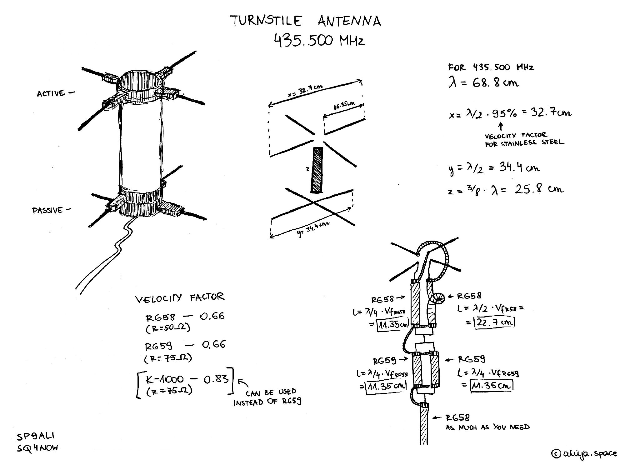
Fig. 1 - Turnstile antenna for 435 Mhz, schematic
If you want to connect the antenna to the SatNOGS station you are going to need a Raspberry Pi, configured with SatNOGS OS image and settings. But it’s, of course, optional - a computer with the SDR is perfectly enough to start your radio adventure.
You can also make the setup better using the LNA (low noise amplifier, that increases the power of very low signal) and a filter to get rid of unwanted radio noise. It’s an option worth considering - my station works without them now and the signal is not the best.
If I write "wavelength" anywhere below, I mean 68.8 cm for 435.500 Mhz. Feel free to modify it for your needs (but remember to take it into account in every calculation).
- Prepare all the materials and tools. 3D print the holders or create them from other available materials. Remember that the two top rods have to be cut in half and there should be some space between them to be able to solder the cable inside the pipe/holders, while the bottom rods have to be whole, but they should not touch each other.
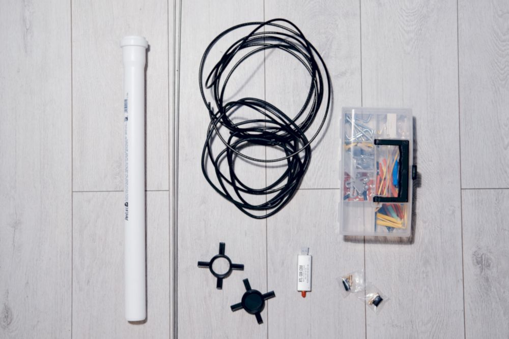
Fig. 2 - Materials for the turnstile antenna
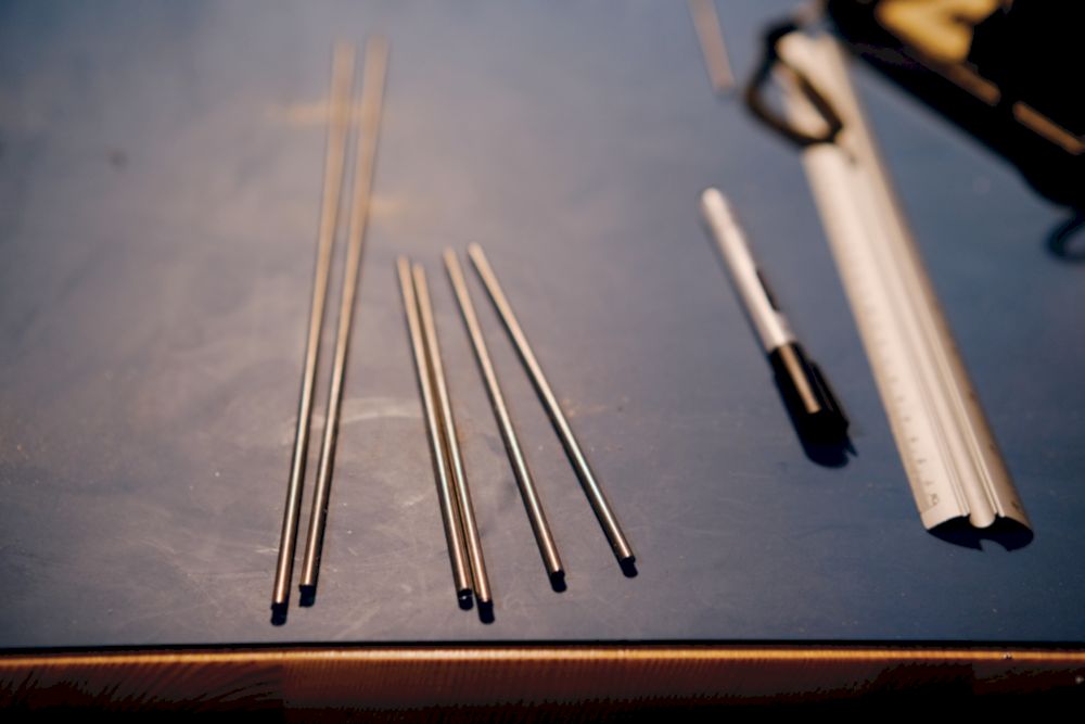
Fig. 3 - Antenna rods
- Cut the rods according to the schematic (Fig. 1). For the top rod (active) it will be half of the wavelength multiplied by the velocity factor for stainless steel. If you chose another material (like copper), please use the velocity factor for this material. 95% for steel gives us 32.7 cm for the whole one top rod, so after cutting it in half, it should be something around 16.35 cm for one piece. Prepare 4 pieces this length. For the bottom rod (passive) use just a length equal to half of the wavelength - 34.4 cm. Prepare 2 pieces this length (Fig. 3).
- While cutting the rods, remember to smooth out their ends a bit. It would be bad to stick the antenna in your eye before even finishing it :).
- Cut the pipe for the desired length - for me, it was ⅜ of wavelength, so 25.8 cm.
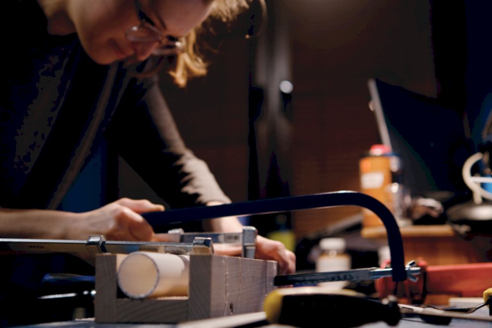
Fig. 4 - Cutting a pipe was fun!

Fig. 5 - Coaxial cable cross-section
- Prepare the cables! That’s where the fun begins. You will need two equal pieces of RG59/K-1000 or any other 75 Ohm cable first. Please note the velocity factor for the chosen cable (it should be in its characteristics). Pieces length should be a quarter of wavelength multiplied by the velocity factor. So, if you choose RG59, it’ll be 11.35 cm for both pieces. Cut the endings, to leave a little part of the inner wires out and also a little bit of shield, so the soldering will be possible (Fig. 5). Do it from both sides of both pieces.
- Put both pieces of cable next to each other (you can glue them with tape) and solder their inner wires together from both sides and the shield together from both sides. The most important thing is: the wire cannot touch the shield. You can check it with a multimeter, just to be sure.
- Prepare RG58 or other 50 Ohm cable. You will need one piece with a length equal to a quarter of a wavelength multiplied by the cable velocity factor and a second piece two times longer. For RG58 it’ll be 11.35 cm and 22.7 cm. Prepare their endings (just like with 70 Ohms) and solder wires and shields, but only from one side.
- Solder these already soldered inner wires and shields from RG58 with RG59. Remember about conduction - use a multimeter to check if there’s no short circuit between the inner wire and the shield.
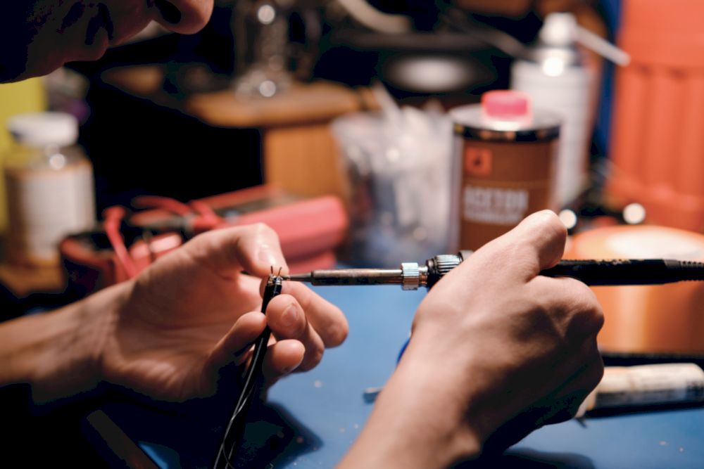
Fig. 6 - Soldering coaxial cable
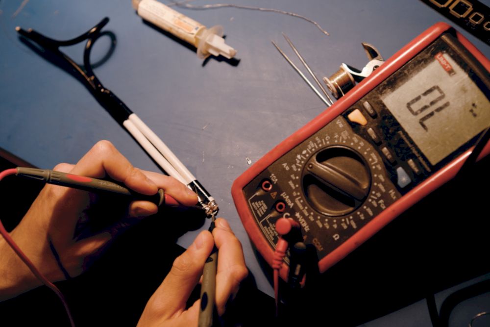
Fig. 7 - Multimeter is your friend!
- Place the rods inside the holders. Attach RG58 endings (the ones that weren’t touched before now) to the rods according to the schematic. Inner wire and shield from one cable should be attached to rods that are opposite to each other - same for the second cable. Be careful and join them precisely. You can solder or screw them to the rods, using a little piece of a jumper cable (but not too long, because it can change the antenna characteristics!). The method doesn’t really matter - what matters is the conduction of the final effect. Again, take your favorite tool and measure if there’s no short circuit anywhere. There should be a circuit between two rods (next to each other) and inner wire at the end of the cables and another circuit between two other rods (next to each other) and the shield.
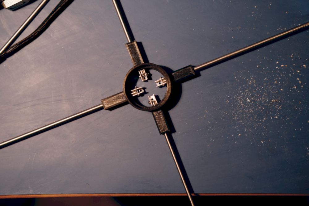
Fig. 8 - Precisely attach cable to the rods
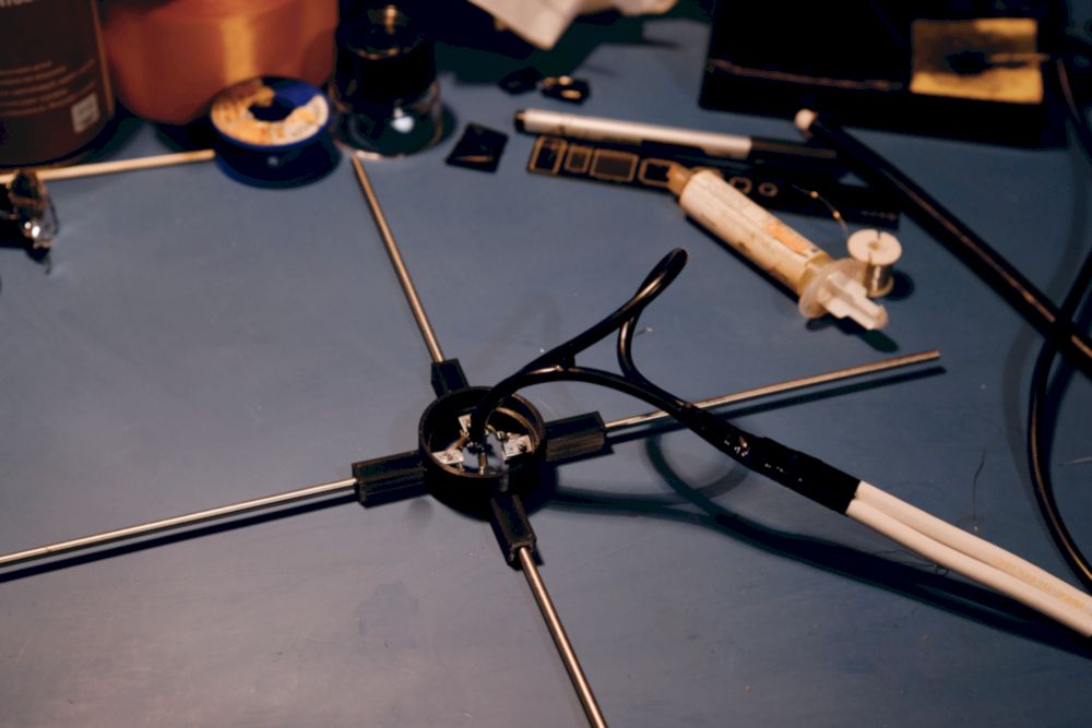
Fig. 9 - Final assembly - cables and rods
- Solder the main coaxial cable (50 Ohm) with the desired length to the already soldered ending of RG59 (just like on the schematic). Remember that this main cable is going to be connected to your computer/RaspberryPi, so it probably needs to be quite long. Solder and tighten the SMA connector at the other end to be able to connect it to the SDR.
- Attach the holder with rods and cable to the main pipe. Prepare the second holder, with the passive rods, and place it in the bottom. Try to make your antenna resistant to weather conditions - you can secure it with glue or any other way you like. If you printed your elements from ABS, remember to choose a glue that will work with this material (there can be problems with common ones).
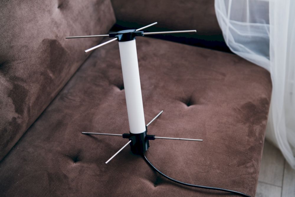
Fig. 10 - The antenna is ready, yay!
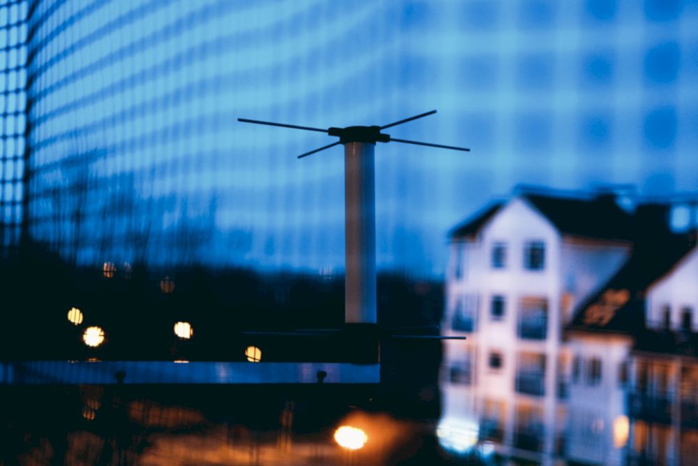
Fig. 11 - ...but it'll definitely work better outside the building
Can I go listen to the satellites now?
YES, YOU CAN!
Just go outside, place the antenna somewhere high (and not in the center of the city if possible), connect it to the SDR, put SDR in your computer’s USB port, run SDR Sharp or any other program and… listen!

Fig. 12 - Listening to the satellites is the best!
But… what can I listen to?
This antenna was calculated to work the best for amateur satellites in the 70 cm band. As you can see in these interesting statistics, the highest number of satellites transmit on 435 to 437 Mhz, so it should work perfectly for them. You can try to catch KRAKsat (it’s always restarting when it’s in sunlight, so quite easy to catch!), KKS-1 with a nice visible CR beacon, or distinctive SpooQy-1. Use tracksat.space or GPredict/Orbitron to calculate satellite’s passes above your location and give it a try!
Just out of curiosity, you can always explore some other frequencies: listen to some random radio on FM frequencies, planes or try to eavesdrop on some other interesting stuff in your area. I assure you - there’s a lot of things going on radiowaves!
What this antenna is not good for? You probably won’t be able to catch some NOAA images and ISS SSTV transmissions - these are conducted on 2m wavelengths (around 144Mhz) and this antenna is not adapted for it. However, I did in fact manage to listen for it a bit, it was mostly a coincidence (and some random radio magic).
Together with Piotr (SQ4NOW, to stick with proper ham radio names :)), we managed to measure the antenna with NanoVNA and the results were good. It has SWR around 1.8 for 435.500 Mhz, and, what is interesting, almost 1 slightly below 400 Mhz! It means that it’s a good antenna for 435 Mhz, but it’s the best antenna for around 380-390 Mhz. Although I tried to catch some satellites on ~400 Mhz, I failed - there is so much noise in my area on these frequencies that it just didn’t work. But you may succeed!
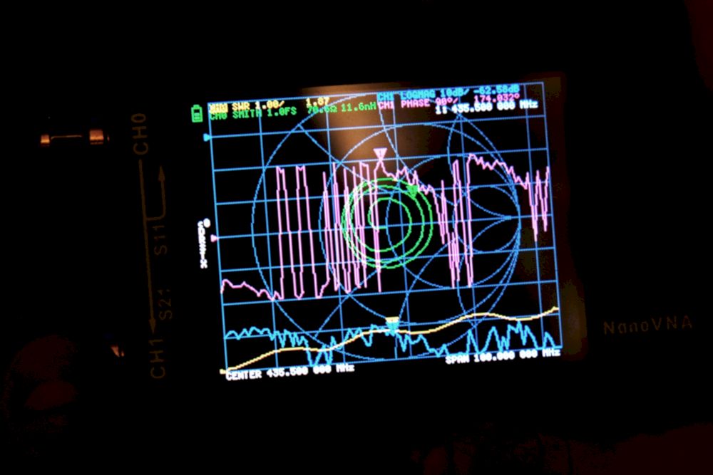
Fig. 13 - 435.500 Mhz - SWR around 1.8 (NanoVNA) - not bad!
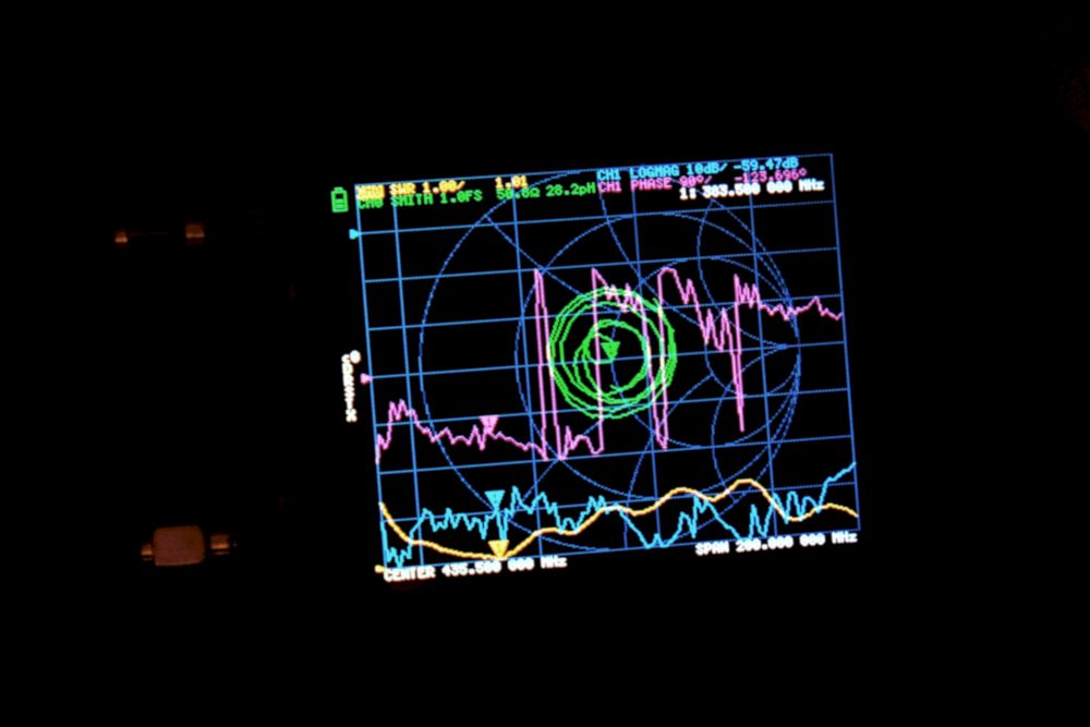
Fig. 14 - 383 Mhz - SWR around 1 (NanoVNA) - surprise!
How to connect the antenna to the SatNOGS network?
Time for the second part of the tutorial - connecting the station to the SatNOGS network. It’s not a complicated process and all you need is a RaspberryPi (version 3 or up is preferred) and a microSD card. The whole operation is quite well explained on SatNOGS website, but I put it into some clear and short points, so maybe it could be easier for someone to use it. Have fun!
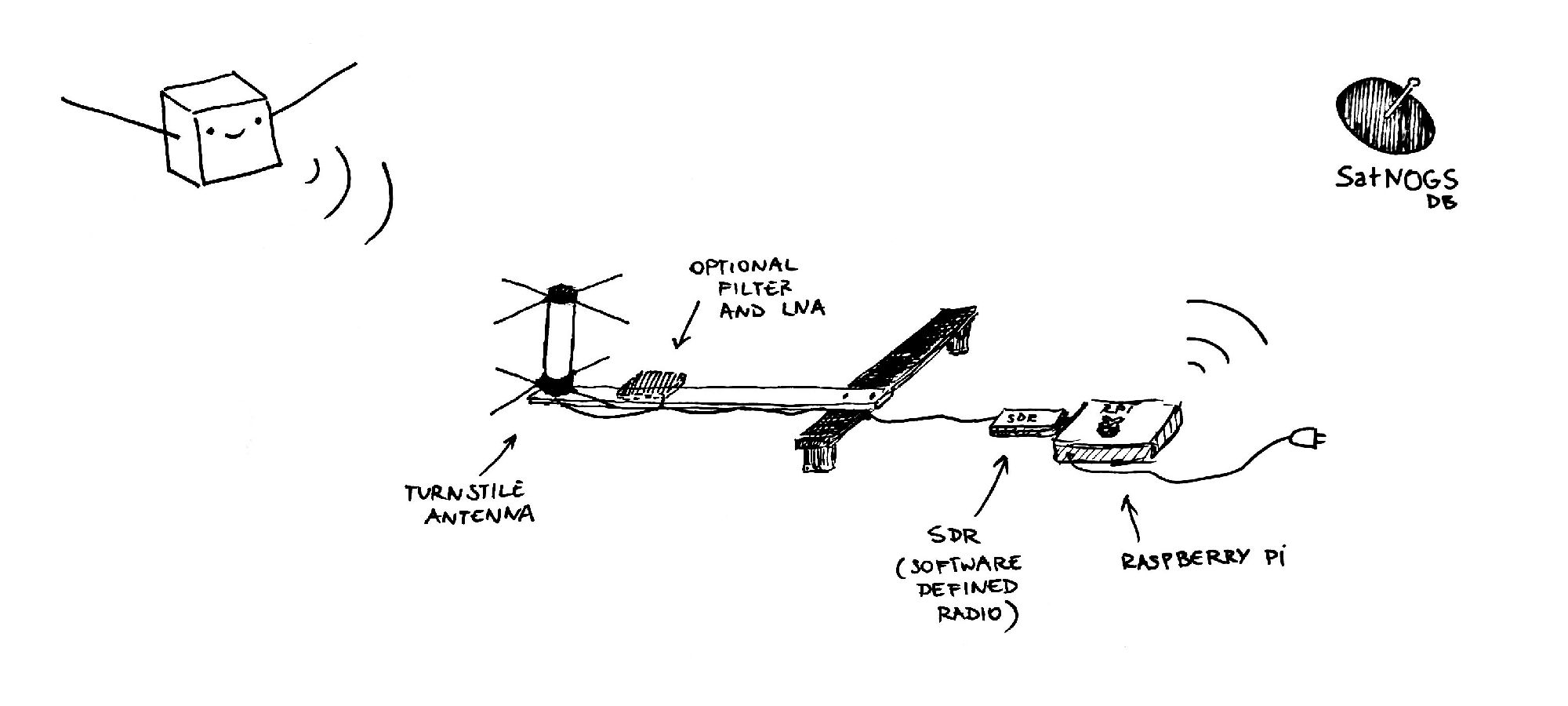
Fig. 15 - Rate my setup
- Create a station in the SatNOGS network.
- Download the SatNOGS OS image and put it into the microSD card using Raspberry Pi Imager software. You can find a good tutorial on how to do it here.
- If you don’t have an external keyboard and monitor you could connect RPi to, put your WiFi details in a special file and place it on the microSD card next to the image. This process is described for example here.
- Put the card inside the RPi and turn it on. You should now be able to access it via SSH.
- Do all the steps from the official SatNOGS site. Remember to configure all the required parameters (I found out that in my image SATNOGS_RF_GAIN was moved to the Advanced settings and it’s one of the most important, so remember to set it too!).
- If everything seems to be working fine, test your antenna with SDR Sharp or other radio software on your computer first. If you confirm that any satellite or other radio stuff can be heard, you can proceed to set up the SatNOGS. It’s good to exclude every possible problem with the antenna or SDR before connecting it to the station.
- It’s working? Let’s connect the SDR to the RPi!
- Use a SatNOGS web interface to calculate the passes and schedule some. You can use the magic keyboard shortcut “S” to schedule a chosen pass.
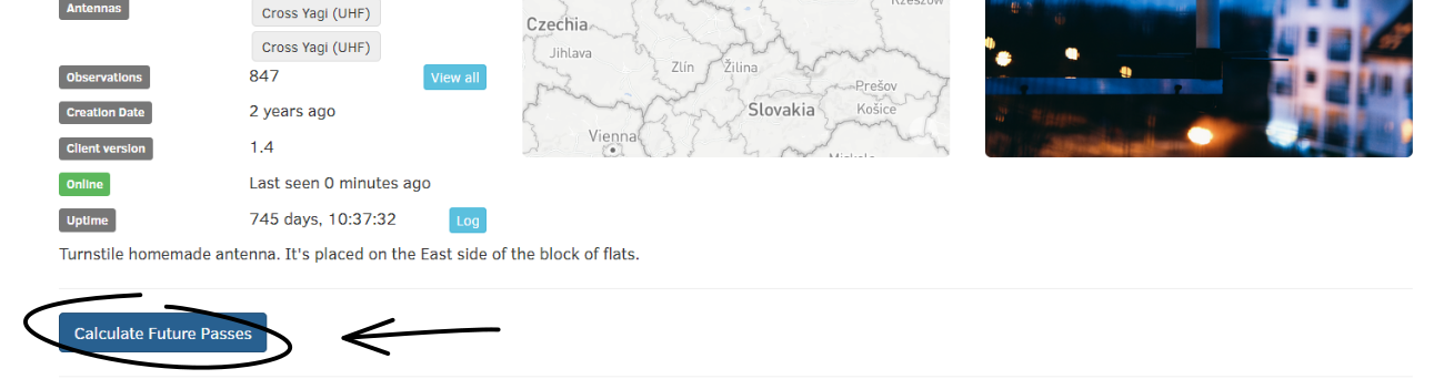
Fig. 16 - Schedule satellite pass on SatNOGS - step 1
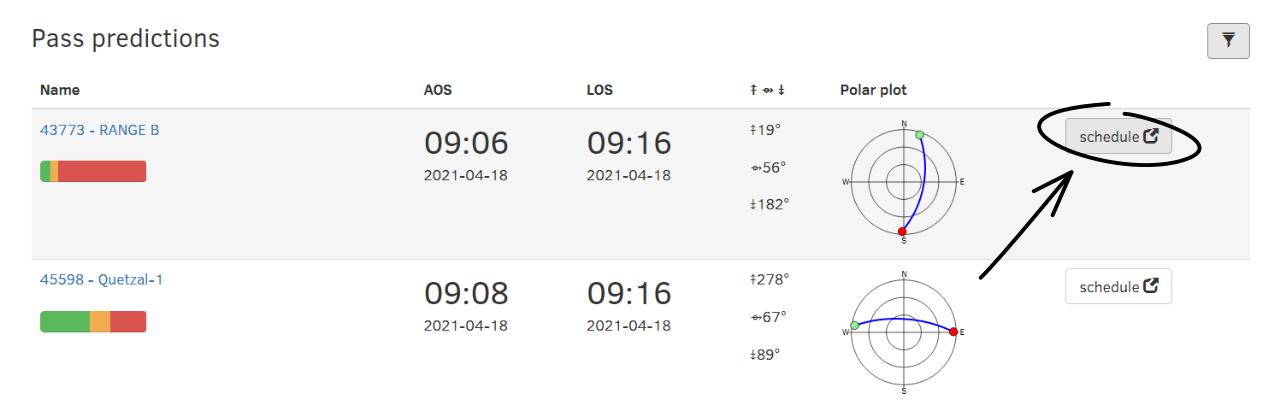
Fig. 17 - Schedule satellite pass on SatNOGS - step 2

Fig. 18 - Schedule satellite pass on SatNOGS - step 3
- Wait for the satellites to fly above you.
- Open the observation and jump with endless happiness! (or… cry in the corner and go to the next chapter).
Did you manage to build the antenna, connect it to SatNOGS and it works? BIG CONGRATS!
But… what if it doesn’t work?
My antenna doesn’t work :( Why?
There are a lot of possible issues. If there’s a problem with SatNOGS itself, have a look into troubleshooting page. For me, the most important setting was SATNOGS_RF_GAIN - I experimented with five or six different values until I found the best one. You can always set the highest possible value here (49.6 dB) and see if it helps with a signal and then, gradually, lower it.
❯ Note: some satellites are not transmitting at all or their beacon interval can be quite long! Don’t give up after a few unsuccessful observations - see which satellites are often caught and start with them :)
If you suspect that the problem is with the antenna itself because you tried it without the SatNOGS setup, you can check the following:
- get the multimeter and measure all the connections - maybe there’s a short circuit somewhere.
- change the location - there’s a possibility that there’s so much noise in your place that it’s literally clogging the SDR. SDR’s range is so wide that all the signals from all the frequencies can disturb your observations. If this is the cause, you can think about placing the narrow filter (e.g. 400-460 Mhz) and LNA very close to the antenna - it could help.
- test the antenna using some ground frequencies (listen to FM radio, try to catch some nearby transmitters). If you don't hear any radio, there's probably something very wrong with your setup.
- find someone with NanoVNA or another SWR meter to measure your antenna and get some information about its characteristics.
I can tell you from personal (but amateur) experience that two things are really important when it comes to antennas: precise soldering and location. The first one is achievable if you spend some time on it, but the second one is harder to fix. If you live in a city center and have a lot of buildings and interferences around, there’s quite a high possibility it’ll be difficult to obtain satisfying results. But it all depends - the easiest way to get to know your conditions is to try! :)
Summarizing…
I hope that this tutorial will be helpful for you. If you have any questions or thoughts about possible improvements, don’t hesitate to write. I’m not an expert if it comes to antennas and radio stuff, but I like to share some interesting projects I’m working on and this antenna was one of them - and as you can see on SatNOGS, it works, yay!
If you build your antenna and manage to listen to some satellites, you can let me know in the comments, I’d love to see some of your creations :).
Section 2: why should I even build an antenna?
So, why?
Besides the most obvious answer (because you can and it’s fun), there’s one even more compelling reason - you will get to know how much there’s happening on radio waves! I’m always impressed by the amount of the data that is transmitted on any frequency all the time - from radio or television, through radio amateurs talking with each other, police, planes and other services, radars, navigation systems, garage remote controllers… and I didn’t even list the satellites here!
The second reason: it’s a totally awesome thing that you can listen to real satellites’ data just literally with a metal stick connected to the computer. It never stops to amaze me! Most student, educational or other amateur satellites transmit a beacon in fixed intervals (every 30 seconds, 3 minutes, 10 minutes… it depends on the device’s settings). So, if there’s a pass above your location and a chosen satellite has this beacon set, there's a high possibility, you can catch one (or more) of them! And catching is one thing - but decoding caught signals is even more thrilling. If the signal is strong enough, you can demodulate it, using software depending on the modulation technique used by the spacecraft, and see what data was sent - of course, if it wasn’t coded somehow. And I’ve good news here - satellites using amateur frequencies (e.g. ~435Mhz regions) shouldn’t have their telemetry encrypted! So if you know how to get the meaning from these random noises sent on the radio waves (and you often can read about it on chosen projects’ websites), you can do it and receive real information from the real space! Woohooo!
❯ Bonus note: if you live somewhere not-so-far-away from the satellite’s ground station and mission control, you can sometimes hear more than only a beacon. Operators can download some more telemetry, photos, or other interesting data from their spacey child - you won’t probably hear the station itself (unless you live a few kilometers from it), but if you can see the outstanding traffic on the waterfalls, these are probably answers for the commands from the ground. Amazing, isn’t it?
To sum it up: it’s basically fun and science. So, just build the antenna!
I know that it’s a little late to ask, but… what is the antenna anyway?
No worries, it’s never too late to ask! Antennas themselves are an extremely fascinating topic, so we can talk about it a bit. If you want to listen to a really good explanation of how antennas work, I recommend this short video. It’s really good for getting the whole idea. But in short words, an antenna is the magic thingy that can change current energy to the electromagnetic waves (if it’s transmitting) or change the electromagnetic waves to the current (if it’s receiving).
We can organize antennas into two categories:
- omnidirectional - that can receive/transmit radio waves in all directions more or less similarly; a turnstile antenna described in the first part of this text is one of them (also some other fancy-sounding ones like an eggbeater, random wire or umbrella).
- directional - according to its name, a one that can transmit/receive radio waves mostly in a particular direction; with the most popular Yagi-Uda, quad or loop.

Fig. 19 - Directional antenna vs. omnidirectional antenna
While directional antennas are often more efficient, they have one big drawback - they are directional. It often means that you need a rotor to be able to follow the satellite passing through the sky - only then the signal would be good enough. With omnidirectional, the process is a lot easier. You just put the antenna somewhere high, in the area without tall buildings or other interrupts and, voilà!, it’s working.
I personally built two antennas before this turnstile one and they were both directional Yagi-Uda. One was based on the really thick wooden bar and it was the best… tool for murder or gouging out eyes. It was so heavy that it was hard for one person to rotate it as the satellite was passing, but it worked quite satisfactorily on an empty field. From the city - nothing could be heard with it. The second one was built in LunAres, during my analog astronaut mission , and it worked quite well (taking into consideration that we put it upright and inside the tent… still impressive!).
This turnstile is my third, but totally number-one when it comes to performance - probably because of Piotr’s soldering skills (thank you once again!).
Bonus paragraph: failures!
The official part, how to build an antenna, is already over, so we go behind the scenes a bit and talk about… how not to build an antenna. While creating this one, I managed to make several silly mistakes, but they can be valuable to learn from if you decide to create one by yourself. So, let’s get started!
The first one included a bad 3D print design. If you look carefully at the Fig. 2 and then, at the Fig. 20, you can probably spot what is wrong… I accidentally designed and printed the bottom holder element as if the rods were meant to be cut in half (or magically go through each other). Probably not gonna happen, so remember about placing the holes in the distance bigger than the rod diameter - so the rods don’t touch each other! You can use my model as a reference for yours (it's of course already fixed).
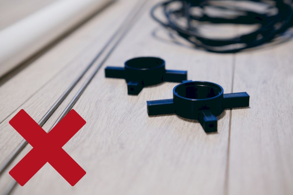
Fig. 20 - Not really the best elements ever...
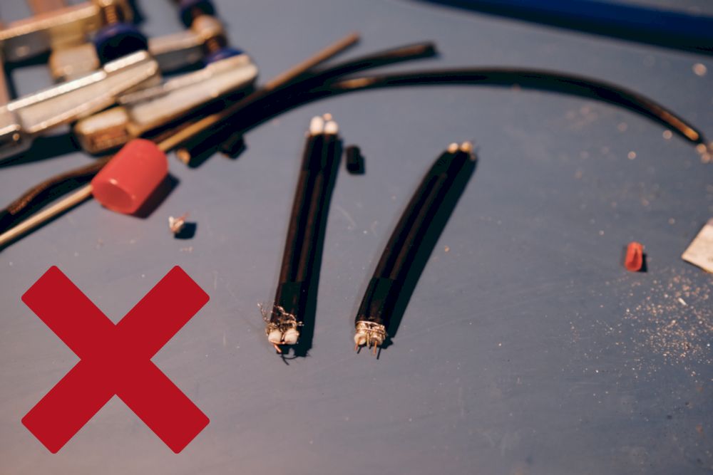
Fig. 21 - always choose cables with a copper shield! (this image is an example of really bad attempt to solder cables that cannot be properly solder. Don't do it like that!)
When the first error was found almost instantly, the second one unfortunately was not. The coaxial cables that I ordered were some random RG58 and RG59 ones, but I didn’t try to solder them earlier. And it was a mistake. It’s really important for the cables to have their shield made from copper, so it’ll be possible to solder it properly. Quality of soldering is one of the critical factors of antenna success, so choose your cables wisely! In the Fig. 21 you can see the flawed cables that we were unable to solder at all. So - remember to check cables before final assembly - it was an extremely unpleasant discovery (repeated twice, so… don’t be like me :)).
And finally… a funny one. Be careful with microSD cards. It turns out that the Raspberry Pi official casing is not prepared to put RPi inside with a card already inserted… Well.
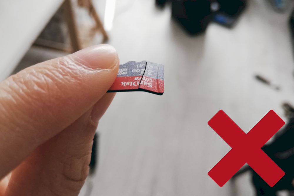
Fig. 22 - Had no idea these are so fragile!
But still - building your own antenna is totally fun, so - don’t hesitate to start your own project!
That’s all!
Thank you very much for the attention! I hope that this tutorial could be helpful for someone who wants to start their antenna adventure and feel some radio waves magic. Below, I included a few links that could also be engaging. Have fun and 73!
- https://www.satblog.info/ - DK3WN amazing blog with loads of information about satellites, receiving, decoders, etc.
- https://airspy.com/download/ - SDR# (SDR Sharp) - software for SDR
- https://sourceforge.net/projects/qtmm/ - AFSK1200 decoder - software you can decode some satellites telemetry with (e.g. KRAKsat)
- https://network.satnogs.org/ - SatNOGS network
- https://www.youtube.com/watch?v=FWCN_uI5ygY - nice video about how antennas and electromagnetic waves work
