Have you ever wanted to see a far-away volcanic eruption’s effect on the Earth’s atmosphere from your own house? After the Hunga Tonga volcano eruption on the 15th of January this year, not only the shockwave circled the globe afterwards, but also numerous photos of data from home weather stations with graphs clearly showing a sudden change in pressure. I’ve always wanted to create a small DIY meteo station but that was the moment I decided – time to open KiCad!
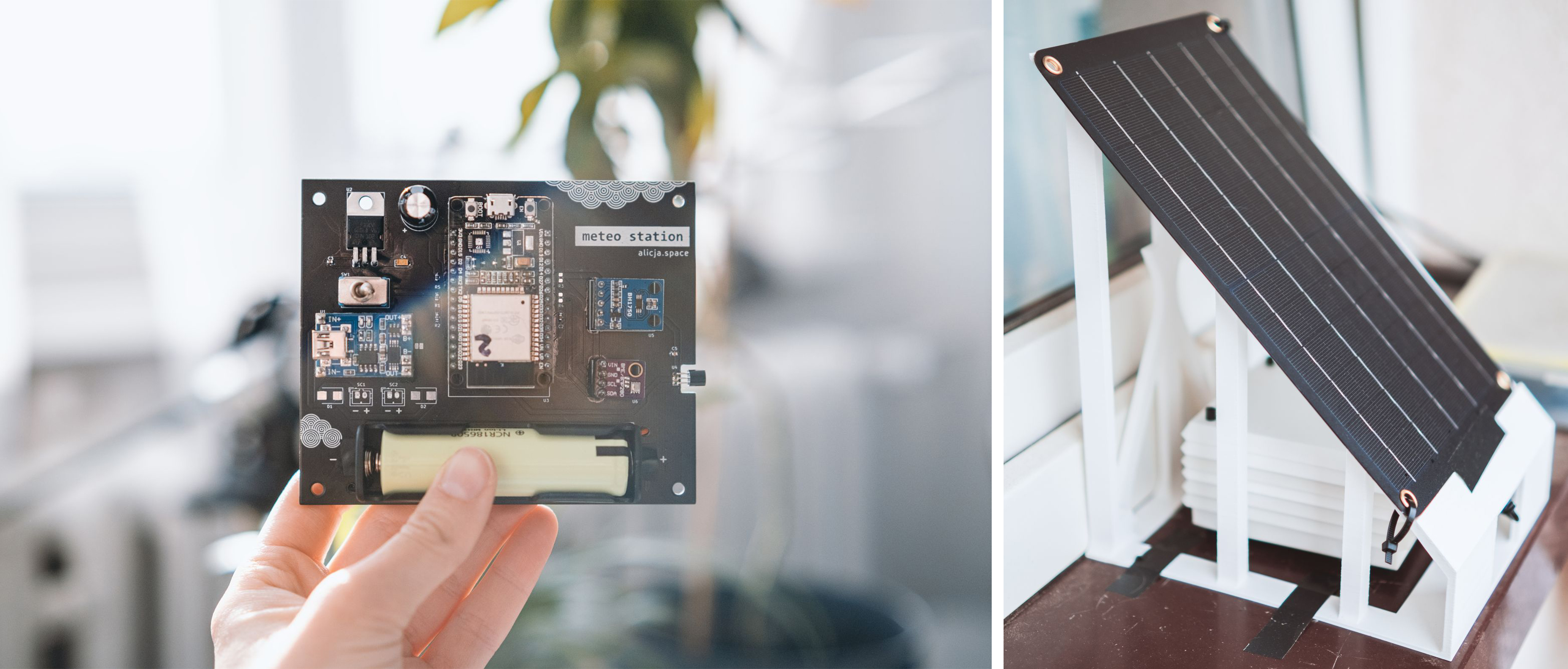
Fig. 1 - PCB and complete meteo station
Before we start…
I should start with a quick disclaimer – I’m neither a professional electronics engineer nor a mechanics specialist. This is my after-hours project designed just for fun, so no specific best principles were used and I wanted to make it enjoyable (it was indeed quite satisfying!) and quick (...well, at least I tried). If you want to follow in my footsteps and create your own weather station, feel free to take my creation as a reference but don’t consider this project as a paragon of virtue.
Holy trinity – PCB, code & 3D print
The meteo station project can be split into three main steps: creating a PCB with sensors, coding stuff for ESP32, and 3D printing parts – solar panel holder and homemade Stevenson cage for electronics. Every step should be adjusted to your needs, as there could be multiple great resourceful solutions at every stage of station design.
As a short introduction: this meteo station is meant to be a DIY self-sufficient weather measuring device. I decided to design it as a simple PCB board with goldpins to stick-in or stick-out individual components and sensors (with ESP32 as a brain) to make it more reusable. All elements could have been integrated on board, but it would be a little bit more expensive and time-consuming to build it this way. I was inspired by a solution created by this guy on Instructables. He did an amazing job and I strongly recommend exploring all his meteo projects as other references for your own design.
Coming back to my project – you can find all three repositories on my Github:
Prerequisites
Software:
- KiCad (I used version 6.0),
- Arduino IDE,
- Autodesk Fusion 360,
- Influx + Grafana on your local server.
Components:
- ESP32 (ESP-WROOM-32) – main computer (with LEDs, LDO, USB-to-UART unsoldered),
- TP4056 – battery charger,
- 18650 battery + holder,
- efficient solar panel – I finally chose DFRobot FIT0601 Monocrystalline Solar Panel (5V, 1A),
- slide switch, LDO etc. – according to the KiCad project BOM.
Sensors I chose:
- BME280 – humidity, pressure, temperature,
- DS18B20 – temperature (sticks out the PCB),
- BH1750 – light (should be mounted on cables, outside of the box).
Other stuff that you may need:
- local server (e.g. RaspberryPi or other computer) with Influx installed (I used version 1.8) and a Grafana instance to gather data from the station and display it in a readable way,
- access to a 3D printer to print a Stevenson cage and solar panel holder,
- screwed spacer sleeves to connect all elements of the Stevenson cage,
- a soldering iron, optionally also a hot-air station, together with all the stuff needed for soldering,
- something to protect the PCB from the rain or other negative environmental impact – I chose PLASTIK 70 varnish.
Enjoy!
PCB design & soldering
Let’s start with a schematic.
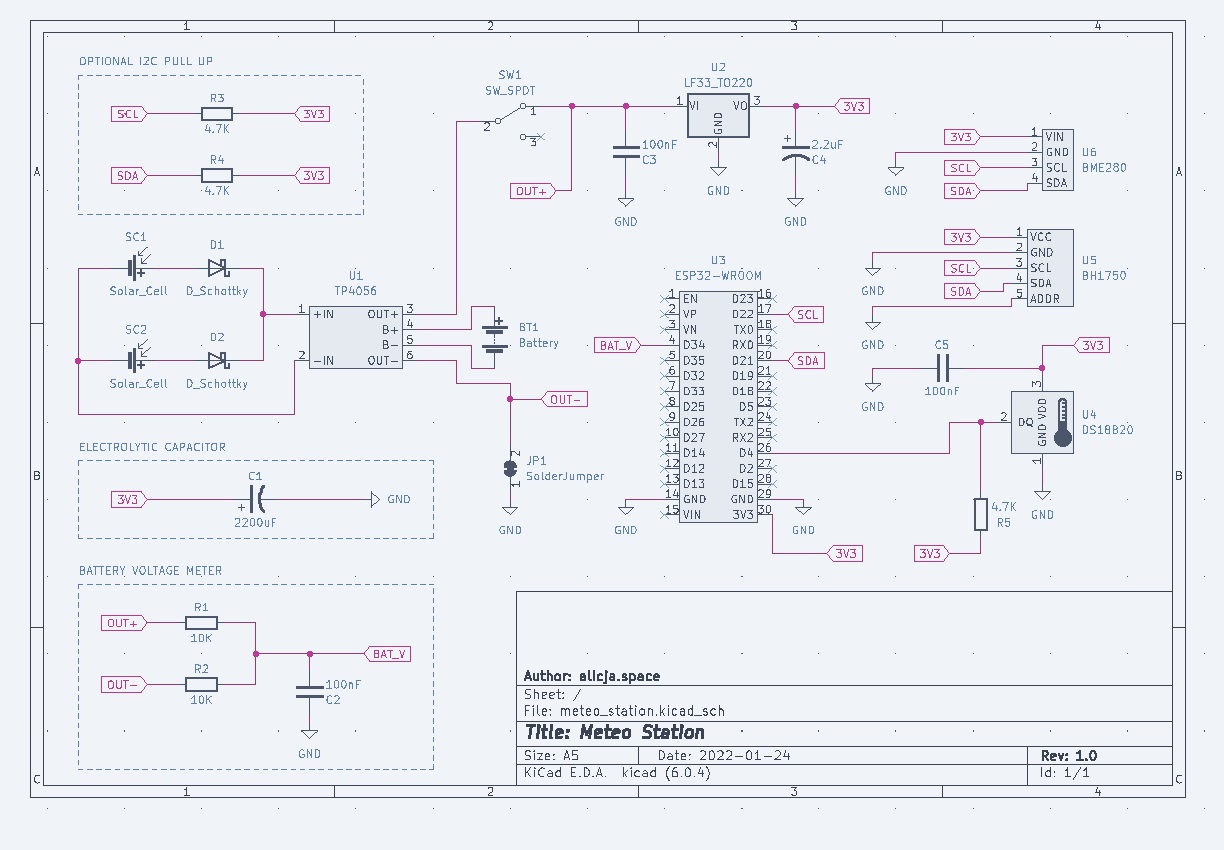
Fig. 2 - meteo station PCB schematics
I decided to make ESP32-WROOM the heart of the meteo station. Why? ESP32 is quite straightforward to work with and it has an embedded WiFi module, which makes storing data on the external server much easier. The current consumption of this microcontroller is also quite satisfactory, but to make it better I had to introduce some custom improvements (but more on that later).
Analyzing the schematics:
- U1 – TP4056 is a standard battery charger with two inputs, two outputs, and two battery pins. Solar cells can be connected directly via mini USB or to inputs (-IN and +IN) with Schottky diodes in parallel. Why Schottky? To avoid a possible reversed current that could destroy the cells, and helps with electricity conduction when one of the multiple panels is in the shadow. In my final project, I haven’t finally soldered neither the cells' connectors nor the Schottkys – I found a solar panel with integrated protection circuit and USB, and it became my first choice.
- SW1 – just a nice big slide switch :)
- U2 – LF33 – LDO voltage regulator with output voltage 3.3V to power ESP32 and sensors. Standard circuit, redrawn from the datasheet with two decoupling capacitors (100 nF on VI and 2.2 uF on VO) to filter noise caused by other elements and reduce its negative effect on the rest of the circuit.
- U3 – ESP32-WROOM – the main heart of the station. All sensors are connected to it – I chose these operating on I2C, so, besides powering and ground, we use only SCL/SDA pins and one digital input for DS18B20 temperature sensor (one wire). If you are planning to include multiple sensors using I2C, make sure that they have different addresses, as they will be connected on the same line.
- U4 – DS18B20 – the most basic temperature sensor you can find on the market. Theoretical accuracy: +/- 0,5°C in the range -10°C to 85°C. Connected according to the datasheet with a pull-up on the data line (via 4.7K resistor) and a decoupling capacitor (100 nF).
- U5 – BH1750 – light sensor, operating on I2C. Nothing unusual – I put an optional pull-up on I2C, as I wasn’t sure if it’s built-in.
- U6 – BME280 – humidity, temperature, and pressure sensor, operating on I2C. As above, nothing unusual, besides an optional pull-up on the I2C line.
- C1 – Electrolytic capacitor – it works as a decoupling capacitor while making the whole system more stable. ESP32 needs a lot of power on startup, and a large capacitor helps to ease the surge in current that the microcontroller needs.
- Battery voltage meter – simple voltage divider, the most popular battery monitoring technique. Two resistors are connected in series and the source voltage is applied across their ends – voltage is divided against them (according to their ohmic values) and can be measured on the ADC input. Nice and effective, as we get the battery level and can easily use its value in code or push it into logs to track how it changes with the weather.
I hope it’s all clear but if you have any questions, don’t hesitate to ask in the comments.
After drawing the schematics, the fun part started – designing the actual PCB board. As I already mentioned, my favorite choice for both activities is Kicad (currently testing the new 6.0 version), as it’s free, open source, and (subjectively) exceptionally convenient.
To be honest, there is no great philosophy regarding the arrangement of elements on the board. I wanted to use some components that I already had, so some resistors or capacitors may seem ridiculously small – it would probably be better (e.g., for debugging) to use slightly larger ones. I needed the charger (U1), especially its USB connector, to be close to the edge, and everything else to be arranged in a way that a board would be comfortable to use. In all four corners, I placed holes for future mounting in a Stevenson's cage.
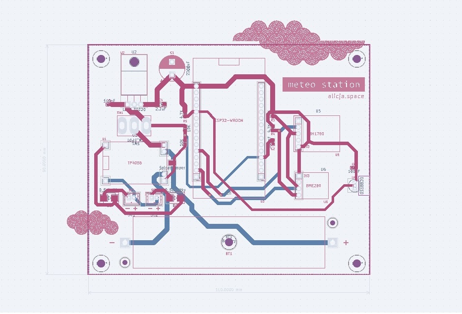
Fig. 3 - PCB design
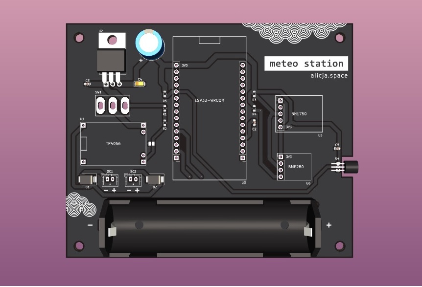
Fig. 4 - PCB render
I have to admit that, personally, I like the final effect – it’s symmetrical and the pattern also came out pretty nice.
Soldering time! Or… desoldering 😬. While the board itself was an enjoyable thing to set up (standard capacitors, resistors, goldpins – maybe a well-spent hour or two with a soldering iron in hand), the ESP32-WROOM suddenly became an issue. After the assembly and programming (with code described in the next chapter), it turned out that it consumes 11.5 mA (!) in the deepest hibernation (!) mode. What could I have done to reduce this consumption? Get rid of “unnecessary” components.
I wouldn’t have this problem if I decided to design a PCB with the integrated ESP32 microcontroller (instead of stick-in/stick-out ready development board) but the die was cast and I had to deal with what I already had.
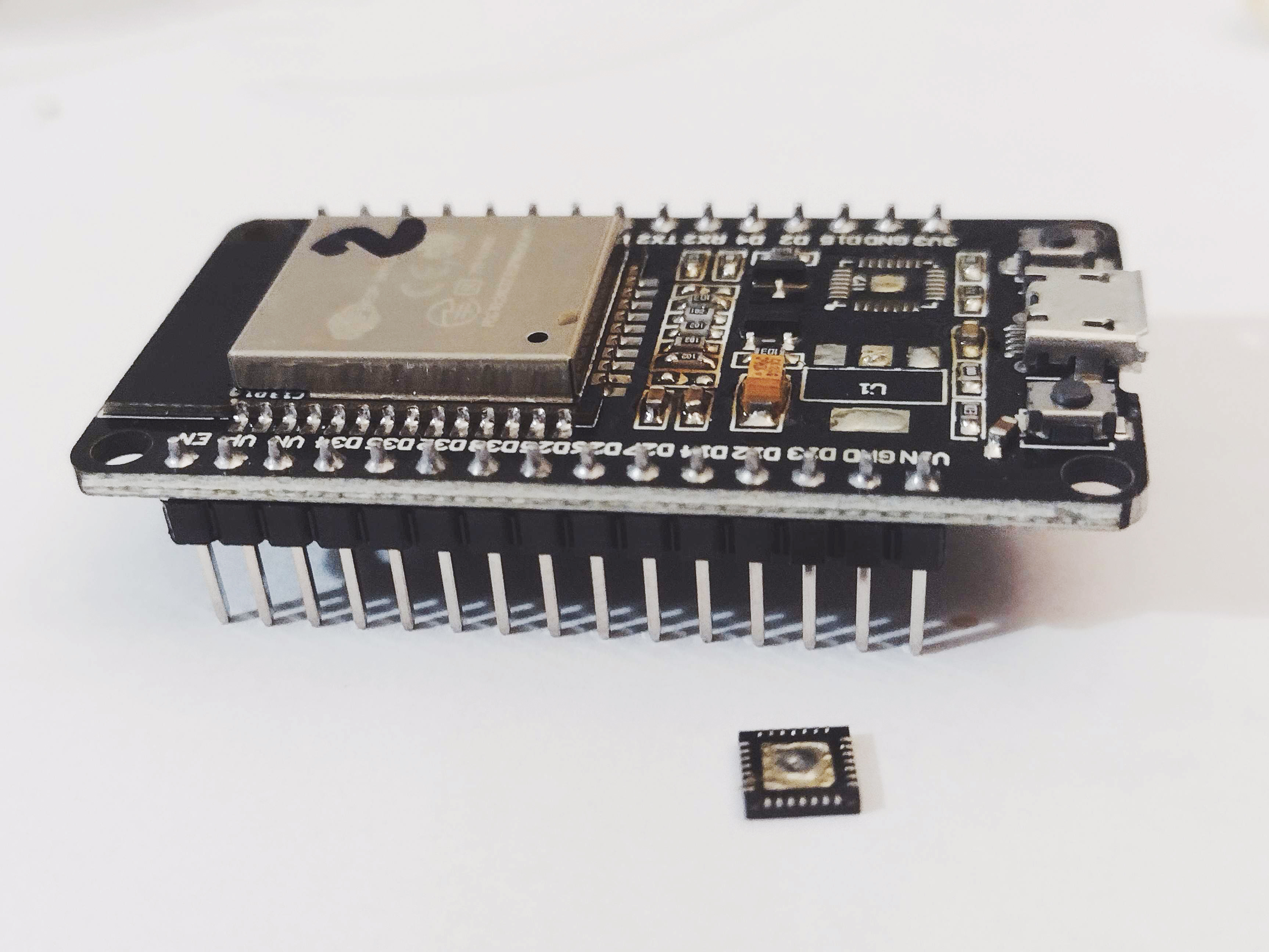
Fig. 5 - Desoldering components from ESP32-WROOM
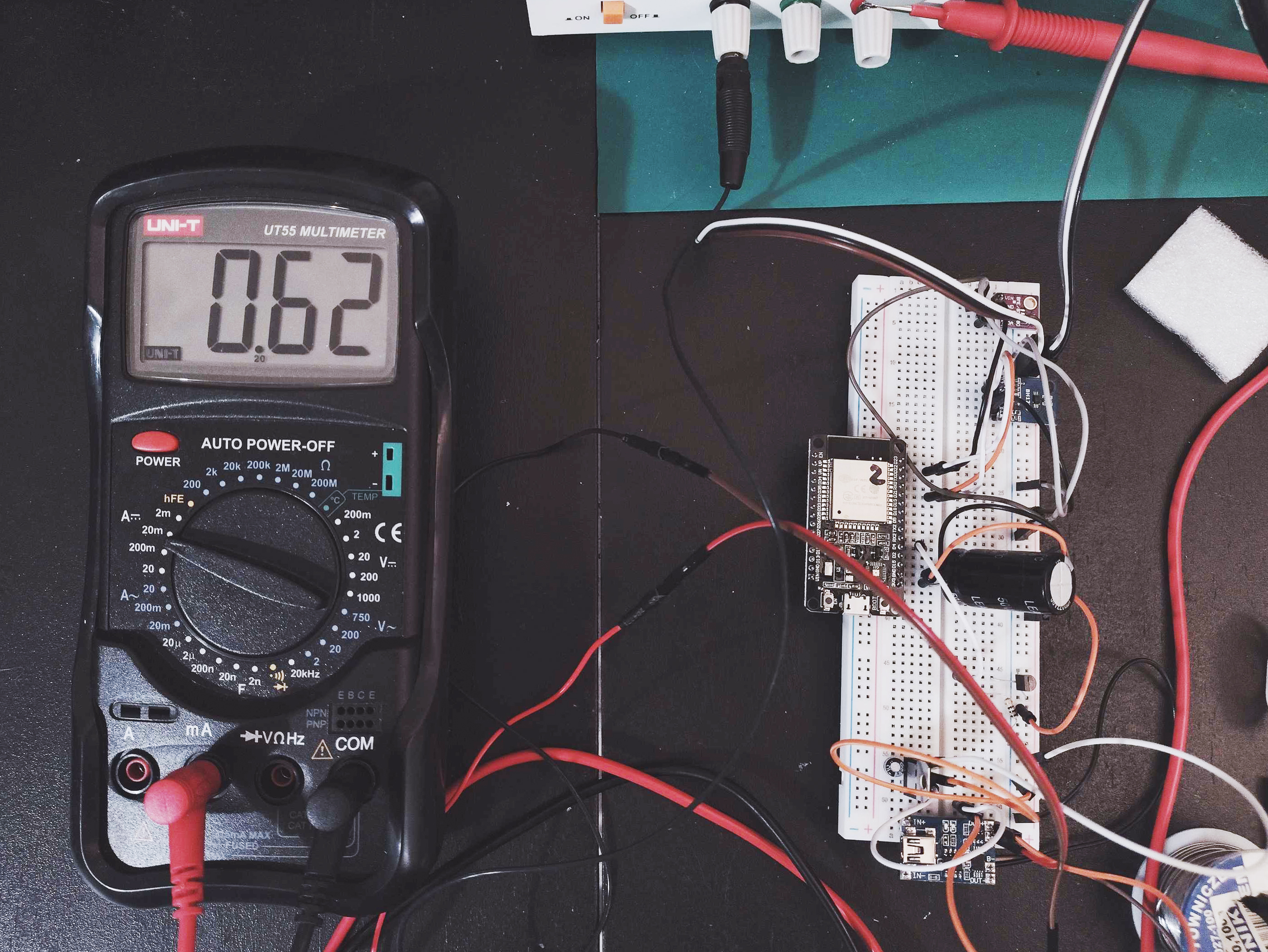
Fig. 6 - Final power consumption - nice!
It’s easier to desolder with a hot-air station (as I did) but it should be possible with a standard soldering iron too. After removing LEDs, power consumption has decreased from 11.5 mA to 9.98 mA; without LDO – it became 8.3 mA; and getting rid of the USB-to-UART converter – 0.62 mA! We got it!
❯ Disclaimer: yes, desoldering USB-to-UART and LDO will make your ESP-32-WROOM inoperable by USB. To power it or program after this operation, you will have to use goldpins (TX/RX) and an external module e.g., FTDI. Quid pro quo :). I assume, however, that eighteen times less (!) power consumption is worth the nuisance.
A finished PCB should be somehow secured from the negative weather conditions – after all, the meteo station will probably be placed outside, and the cage doesn't offer 100% protection. Although this isn’t outer space and the environmental influence is less dreadful than satellites experience in orbit, we should still care to limit the negative impact of rain, snow, or high air humidity on our board. For that, I used PLASTIK 70 varnish. I separated individual components from each other, secured the connectors (and sensors! that's important!) with masking tape – and thoroughly coated everything with lacquer. I left it to completely dry and put on a second layer. After these operations, it’s good to check whether no connectors were blocked during the process, assemble the whole station PCB, and check if everything works properly.
If yes, congrats! Your hardware is ready.
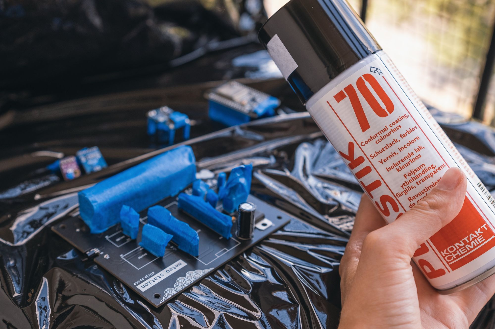
Fig. 7 - Securing the PCB from weather conditions
Code for ESP32
This chapter doesn't really need much explanation – maybe only a disclaimer that this code was created in the simplest and fastest form possible. It’s not perfect as it was (for me) not meant to be; it was just supposed to work. I know my disadvantages and the (im)possibility of focusing on things I don’t really enjoy, so I’m pretty sure that if I wanted to make this code sublime and exemplary (e.g. with LibOpenCM3), it would take forever.
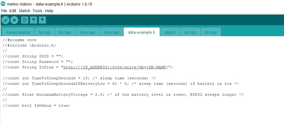
Fig. 8 - Header file with settings
The code was written in Arduino IDE and prerequisites are described fully in the readme but in short: you need the IDE with ESP32 added, some libraries for sensors, and another server with Influx (v. 1.8). Influx should be running on port 8086 (or you should change the settings in the code if it’s different).
For the code to run, you need to only copy data-example.h and rename it to data.h. Uncomment all lines and fill the file with your values:
- SSID - your WiFi name,
- Password = your WiFi password,
- Influx = fill [IP_ADDRESS] and [DB-NAME] fields with your Influx instance data.
After programming your ESP32-WROOM, it should work right away. If there are any problems, you can set the IsDebug variable to True to see additional debugging logs (via UART).
I recommend programming ESP32 before desoldering components from it – it's easier that way (but there’s a big chance you’ll have to adjust ESP32 sleeping time in the future, so you probably won't avoid playing with TX/RX programming with an external board).
The code sets the microcontroller CPU’s frequency to the lowest available and puts it to hardcore hibernation sleep mode – so hardcore that it doesn't even remember the reboot number :). There is also a very basic kind of software hysteresis implemented to try to avoid boot loops if there’s a low battery level. Theoretically, TP4056 should be responsible for that but ESP32 likes to consume a lot of power at start, so even though I put a big electrolytic capacitor there, some problems can occur. The hysteresis is performed in the form of an “if” – if the battery in the current reading is lower than an adjustable variable, then “go to sleep” for a longer period of time.
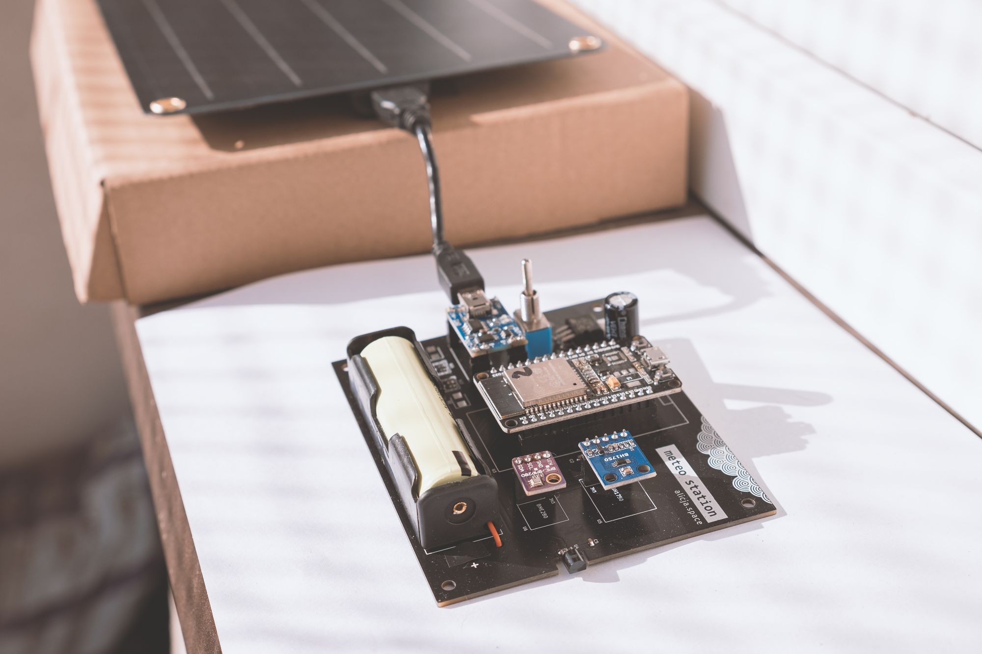
Fig. 9 - First tests of the assembled board outside
Influx & Grafana to store and display data
Every true meteo station™ should have its data nicely visualized. In this topic, I also chose the simplest solution – ESP32-WROOM sends data directly to the Influx database (on an external server, Raspberry Pi) that exposes a default Grafana dashboard with charts, available from my local network. As it’s basic telemetry data, the time-series type of database should probably be the first choice.
I used Influx in version 1.8, so if you want to use my code “as it is”, you should probably stick to this version. I will not elaborate on this topic – more information can be found in tutorials on the official Influx websites.
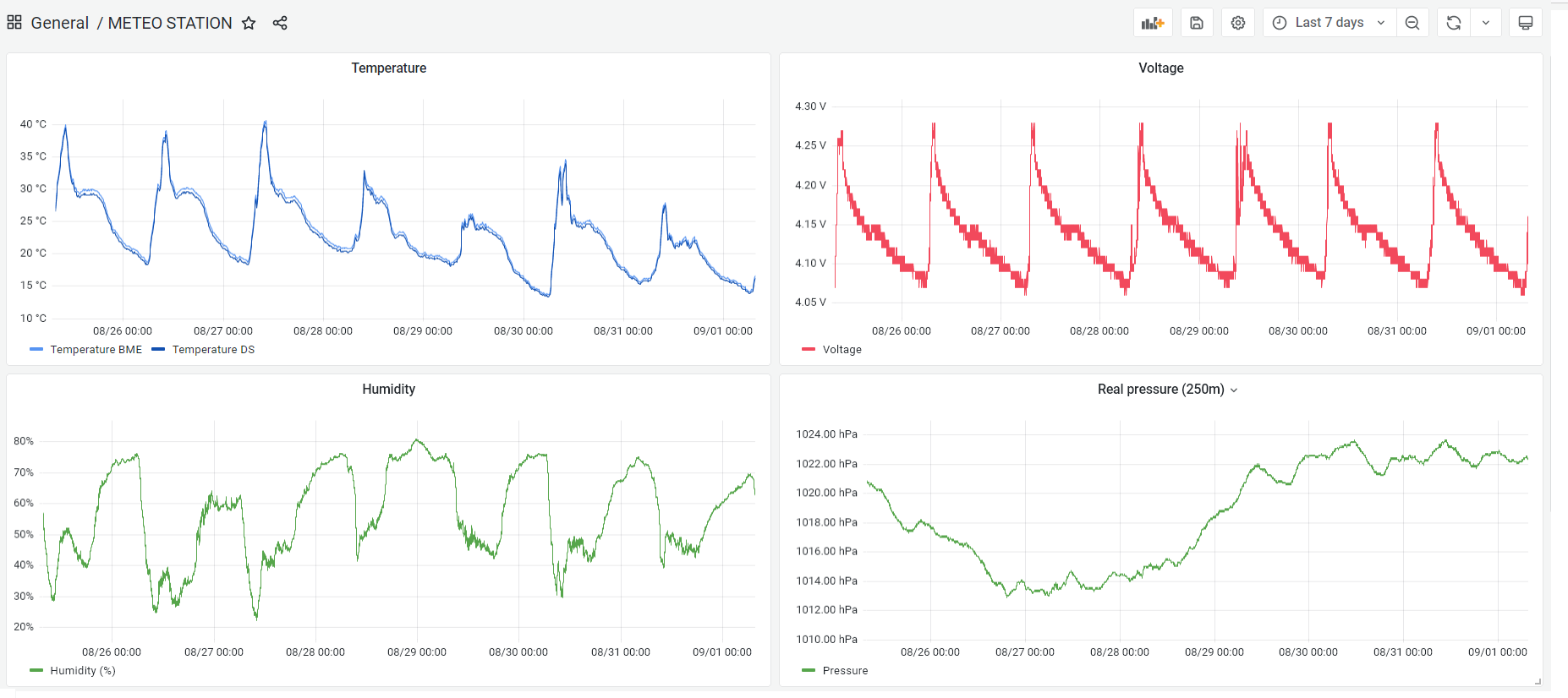
Fig. 10 - Screenshot from Grafana with meteo charts
3D printing
Professional meteo stations are usually kept inside Stevenson cages. These are white boxes with holes/slots that allow air to flow freely through their interior – but at the same time, they protect the electronics from exposure to rain, snow, or direct sun rays. I wanted to create something similar, together with a holder for my slightly-too-big solar panel. And it turned out to be… a challenge. As much as I enjoy 3D printing some custom stuff I design (like the A-1 rocket), I don't really like designing things that have to fit mechanically into other elements. Especially when “other elements” mean a king-sized solar panel that needs a holder at the limit of my 3D printer's capacity.
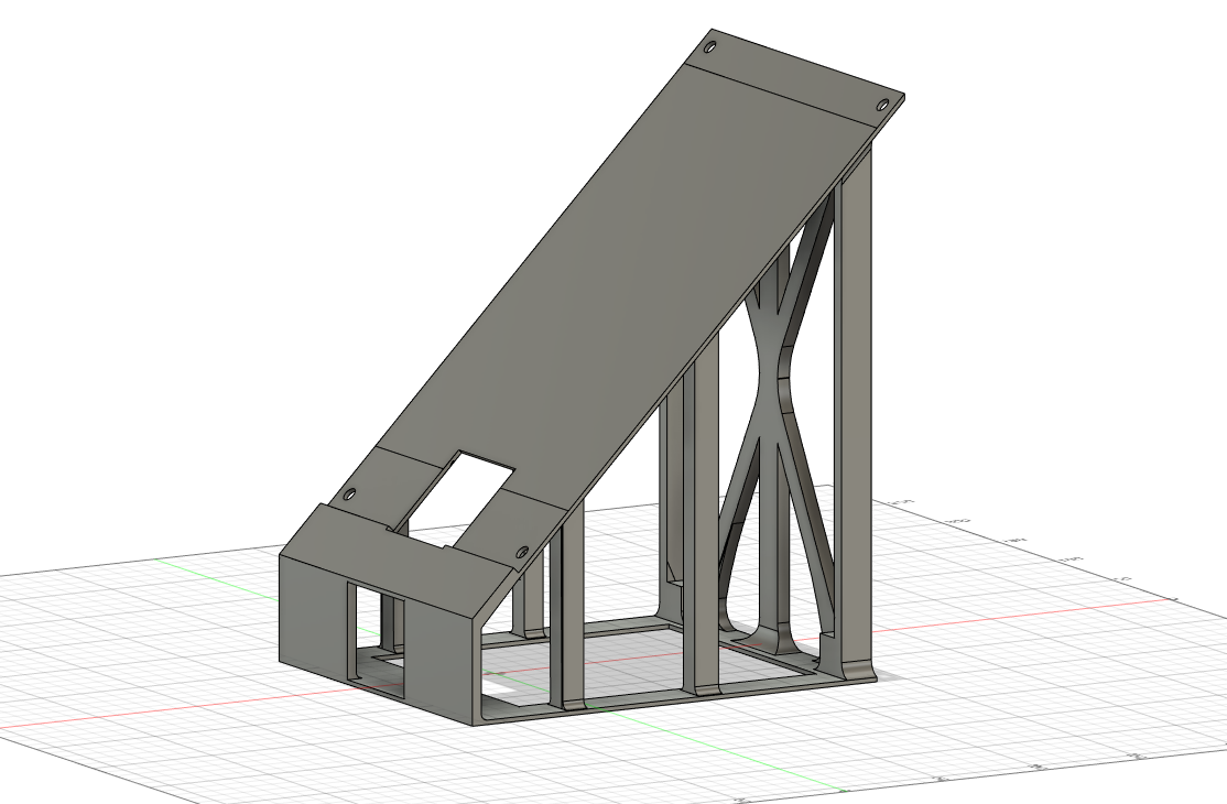
Fig. 11 - Solar panel holder - 3D print project
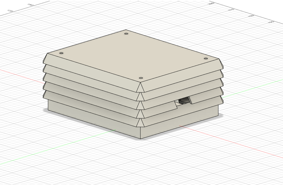
Fig. 12 - Stevenson cage - 3D print project
To be honest, it took me ages to get down to the actual designing and creating this print. Starting in April (theoretically), I managed to procrastinate it until July… Well, some projects are like cheese – they have to mature.
All 3D prints were designed by me (in pain) using Autodesk Fusion 360. If you are professionally connected to mechanics, please do not judge this design – I made it without going into the principles of designing the perfect mechanics. Sorry in advance :).
The printing of the holder was the biggest and the longest print I’ve ever done on my Ender 5 Pro, and the first attempts were quite pathetic. In the end, however, I managed to create something that worked and was relatively fit to the solar panel. Stevenson cage’s layers and PCB were connected using screwed spacer sleeves. The solar panel could be attached with normal screws, or, in my case, with a cable tie (as I didn’t find any properly-sized screws).
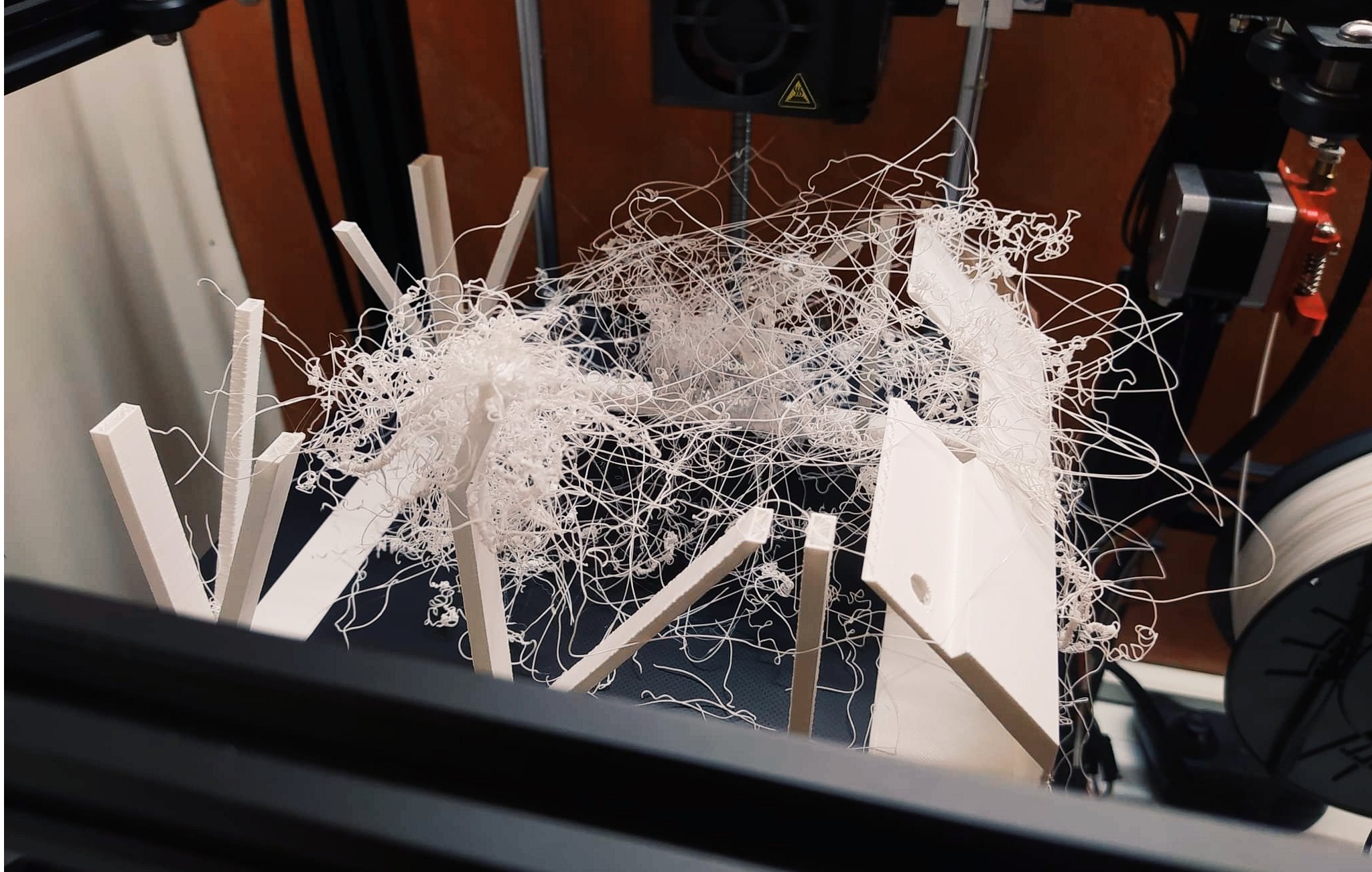
Fig. 13 - Accidental spaghetti...
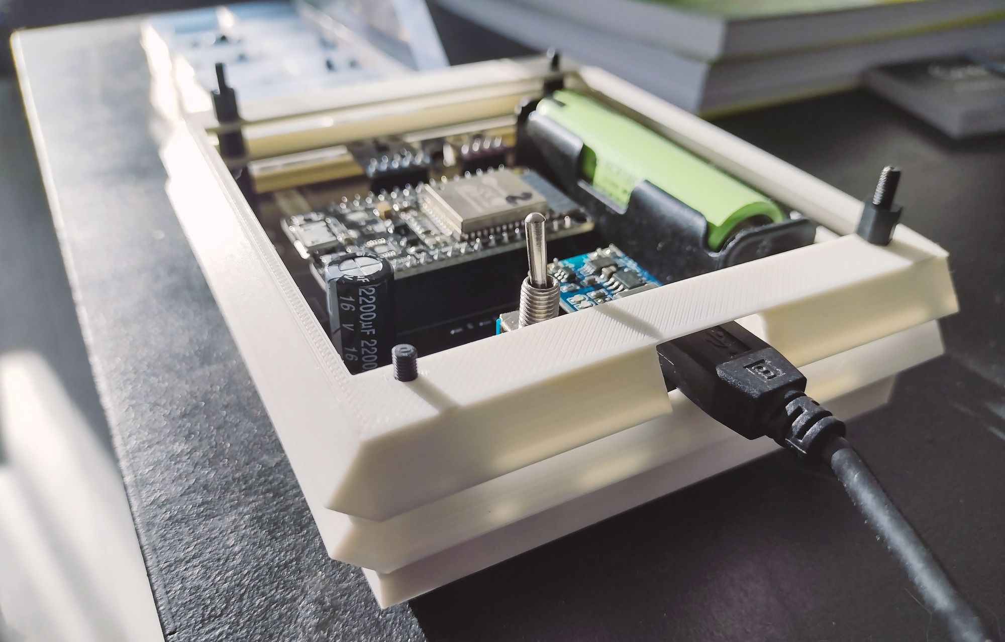
Fig. 14 - Stevenson cage - assembly process
Time for the final assembly!
I set up the final meteo station on the 4th of August 2022. Today, on the 23rd of September, it’s still working as it should, which makes me really satisfied. The station maybe doesn’t look very profesional but it acquires all the data I wanted – and I can now peacefully wait for the volcanic eruption to happen somewhere :).
ESP32 sleeping time is set for 15 seconds now which gives a data point every 20-25 seconds. So far, the battery has never run out of power, although there sometimes happen a few darker days in a row when the voltage drops significantly. Usually, however, one sunny day after such a series is enough to recharge the battery to full. I don't know what the chart will look like in winter, but in case of power issues, I will simply change the ESP32 hibernation time in code to a bigger value.

Fig. 15 - Final effect! Yes, I admit, I have only one good photo of the station from the window 🙈
I identified some things that could be improved in future versions of the project, including:
- a hole to place a lightning sensor near the solar panel somewhere (with a cable going to the Stevenson cage),
- smaller (but still effective) solar panel,
- designing the Stevenson cage in a way that it holds the PCB aslant.
If you ever design your own station, you are welcome to use my experience as a hint for your own project. 10/10, would build again!
Maybe it’s not rocket science…
…and the project is not even connected to the space industry but I decided to write this short summary of its development as it may inspire someone (you?) to do their own design or just to create something new. It is satisfying to look into my own weather charts every day, analyzing the temperatures and humidity or calculating if the battery is going to survive another cloudy rainy morning. Fun! :)
References
- Github repository meteo station PCB: https://github.com/alicjamusial/meteo-station-pcb
- Github repository meteo station code: https://github.com/alicjamusial/meteo-station-code
- Github repository meteo station 3D print: https://github.com/alicjamusial/meteo-station-3d-print
- Installing ESP32 board in Arduino IDE: https://randomnerdtutorials.com/installing-the-esp32-board-in-arduino-ide-windows-instructions/ [access: 23.09.2022]
- Nice tutorial on a DIY weather station: https://www.instructables.com/Solar-Powered-WiFi-Weather-Station-V20/ [access: 23.09.2022]
- Nice tutorial on a DIY weather station, from the same guy, a new version: https://www.instructables.com/Solar-Powered-WiFi-Weather-Station-V30/ [access: 23.09.2022]
- Guide to ESP32 hibernation modes: https://www.mischianti.org/2021/03/15/esp32-practical-power-saving-deep-sleep-and-hibernation-3/ [access: 23.09.2022]